820-3787 - Green Light - No Fan Spin - Pulls 28ma

Jameswis

Member
a1398- Was working, and would randomly shutoff. But I was able to turn it back on. Went on like this for quite a while. At 1st, I thought it was a software issue as it seemed to happen more when using Google Chrome, but one day it happened and it just wouldn't turn back on...
- No liquid damage
-No burnt or charred spots
-I don't see any components where the smoke was let out, but that usually comes after I start working on it a bit. :)
-I don't see any parts that look odd in my microscope either. No cracks or chips missing or blown out centers and so on..
-Green charge light turns to Orange right away.
-Same from 4.25amp Magsafe2 and from Bench PSU with adapter for Magsafe2 purchased from Digikey. And Magsafe 2 cable from Ebay (i know, i know...)
-Removed SSD, WIFI, Battery, and Board from Case.
-Nothing gets hot when plugged in, checked by feel and by FLIR Thermal Camera.
-I've been trying to check power rails, but I'm struggling with reading the schematics...
-From what I can tell, PP3V42_G3H seems good at 3.3v
-U7501 Enable Pin4 p5vs4_en=0.86v ------ Pin12 smc_pm_g2_en=3.3v ------ Pin21 p3v3s5_en=3.3v --------

2 Issues I have right now that bug me the most -
#1, I'm not sure how to figure out what voltages I should have and where...
#2, I'm not sure how to read a schematic like this... lol

I'm not sure if this is helpful, but i get 12.57 on all the caps at the top of the board. C9321,C9322 and so on...
C8030 only gets 0.40v on pin1... IDK if thats right or not...

Thanks for your help.
Please let me know where i should probe and what voltages i'm looking for or resistance..
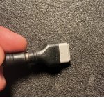
Aslo, attached is a picture of the adapter I purchased from DigiKey.. 20210703_222652.jpg
 
Last edited:

TCRScircuit

Super Moderator
Staff member
OK. First off, you need to use a OEM 85W MagSafe 2. If you use a lower wattage or shitty knockoff, PM_BATLOW_L will be held low and the board will not start.

Look on the power aliases page of the schematic. You need all "Always Present" G3H or G3 Hot rails before S5 rails. You need all S5 rails before S4 rails. You need all S4 rails before S3, and all S3 before S0. You likely are missing PM_SLP_S4_L, which requires PM_BATLOW_L to be asserted to enable.

The random crashing is likely caused by failing CPU MOSFETs. Replace them with FDMF3030 chips after you solve the power issue.

Stop using that charger adapter and get a OEM Apple 85w MagSafe 2. You can cut the cord off and hook it to a DCPS if you want at a later time.
 

2informaticos

Administrator
Staff member
Forget such kind of adapters; never use it again.
A technician need original chargers for service.
However, spare cables (especially 85W Magsafe 1 AND 2) must be available.
This way can discard a leakage input issue, as the original charger will get in protection mode and will not deliver power in such case.
Original Apple chargers have an embedded procesor, dedicated for tihis job.

Test actual charger and spare cable with other MacBook and check the power in system report.
However, this machine can boot with 45/60W charger, ONLY if battery is connected and holds some charge.

Described symptoms denote FDMF6808N issue, which is classic for all the boards using this chip on CPU power supply.
If you get the board starting again, will need to change them; or run some script (software mod), which affects CPU power states.

Now, focus on the power on sequence.
Do you actually get 3V3_SUS?
If PM_BATLOW_L doesn't get high with charger alone, be sure the battery is charging and let it connected.
Then trigger SMC_ONOFF_L and check for drop pulse at PM_PWRBTN_L.
If yes, check for pulse at PM_SLP_S4_L at same time.
Read "HOW TO collection" thread, if needed.
 

Jameswis

Member
Like I said, I have a Magsafe2 4.25amp APPLE brand charger (85w) and it still does that same.
I'll check on the other stuff when I get home.
As for the "always present" part in the schematic, I just don't see that anywhere...
Im attaching a link for the schematic i'm using, if you could please show me where it is, I'd be greatful.
And could you post a link for the "how to collection" thread your referring to, as I'm unable to find it searching.
Thanks,
James
 
Last edited:

2informaticos

Administrator
Staff member
"Always present" is a generic reference, not a signal to search in schematic.
And the other member clearly specified "G3H" for such signal class; like PPBUS_G3H, 3V42_G3H, DCIN_G3H...


Jameswis

Member
I know the "always present" isn't a signal or specific test point for any one thing, but I've seen in other schematics where there is a section that actually says "always present"....
I wasn't sure if the schematic i was using just didn't have it labeled, called it something different, or just what. The other member did say to look on the power aliases page, and that I would need the "always present" G3H or G3 Hot rails...
With the risk of having my head bitten off for saying this, I'm going to anyways...
I've already said I'm not sure how to read this schematic, and without a section specifically saying "always present" (which ive seen on other schematics) and I'm not sure if everything with "G3H" in its name needs to be on or not... And I don't know what voltages should be on what when I do test them, so I wouldn't know if they are out of spec or not... I'm still very much in the early stages of learning, so please understand that sometimes I may need additional information or something explained in a different way... I've always struggled, my entire life, when 1st starting to learn something new. I tend to start out learning really slow, and a lot of times I don't pickup on things when I read them. But once I'm going, I absorb information super fast, except for if I'm reading it.. (most of the time) I usually have to read something 4-5 times and very rarely can tell you what it was about or even recall parts of it. I'm an extreme example of a "hands on" type learner.. But enough about that.. Sorry for the side track there..

Thanks for the link to the "How To Collection", I'm going to review it now, then test around the board. I'll report back once I'm done. Happy 4th of July, and Have a great weekend!!
 

2informaticos

Administrator
Staff member
I'm not sure about your reaction.
I only know that I didn't criticized you in anyway.
I was thinking you didn't exactly understand that message and tried to help you.

I appreciate any people who takes his time and study by himself.
For more information about system power/sleep states:

BTW, welcome to the forum!
I forgot this in my first post...
 

Jameswis

Member
So I've tested some rails, and read through the How To guide.. (Do i really need a jumper wire from SMC_ONOFF_L, to gnd to try and turn the system on while its outside the case? It makes sense you'd need a power switch, but for some reason I don't think ive ever seen Louis use such a setup to get boards to power on in any of his video's i've watched...
Anyways ... My readings:
PP3V42_G3H = 3.3v
P3V42G3H_SW=3.3v
P3V42G3H_FB=1.39v
P3V42G3H_SHDN_L=19.2
PPBUS_G3H= 12.5v
PPVIN_G3H_P3V42G3H=19.2v

PM_PWRBTN_L = 1.28v (drops to 0 when pressing pushbutton installed on SMC_ONOFF_L)
PP3V3_SUS = 0.0v
PM_BATLOW_L = 0.0v
"Then trigger SMC_ONOFF_L and check for drop pulse at PM_PWRBTN_L" Still shows 0.0v
Checked at same time PM_SLP_S4_L= 0.0V

Thanks Again, and if you could please take a look at the info I posted and let me know if those voltages look good or which ones are not, and then please provide me with the next test points so I may continue attempting my repairs.
Thanks
James
Happy 4th of July
 

2informaticos

Administrator
Staff member
iCore boards should start automatically, when charger is connected.
SMC_ONOFF_L trigger method is used for testing signals reaction, when the board doesn't turn on.

"If PM_BATLOW_L doesn't get high with charger alone, be sure the battery is charging and let it connected."
Did that?
No reason to expect board turns on with charger alone, if no PM_BATLOW_L present; that was already explain.
Check now all PCH's RTC signals.
 

Jameswis

Member
OK. I, so I'm confused.... I don't have fan spin regardless. That would be the board powering on. I Thought with only an 85w charger this board would get fan spin when operating correctly?
I'm lost on what you're trying to tell me to do with the battery... I can't really test the board if its in the laptop connected to the battery, and 99% of all the macboard repair videos i've seen on Rossmann's youtube, he doesn't have a battery connected...
So I'm really misunderstanding something here...
And with the numbers I posted from last night, are they good, bad, don't matter? I'd like to know which are testing as they should if you could please let me know that as well.
And after reconnecting the mainboard in the chassis, i get this with the battery connected... Now I'm taking the board back out. lol
With battery connected and charger:
PM_SLP_S4_L=0.0v
PM_BATLOW_L=0.3v (with battery)
PM_BATLOW_L=0.0v(without battery)
I'll check the PCH's RTC signals today... (once i figure out what that is)
I hope everyone had a good 4th, and if you're celebrating today.. Than happy 250th US anniversary.
 

Jameswis

Member
I think this is what you're asking for, based on the How To guide.
RTC_RESET_L = 3.3v
PCH_SRTC_RST_L = 3.3
PCH_INTRUDER_L =3.3
PCH_INTVRMEN =3.3
 

2informaticos

Administrator
Staff member
"I can't really test the board if its in the laptop connected to the battery"
And do not remove the battery?
If board tries to start with both charger and battery connected, that will help a lot; meaning the problem is on power input, not in the rest of board.

Your board doesn't turn on, so I INSIST on the mentioned tests triggering SMC_ONOFF_L signal.
I already know PM_SLP_S4_L is low, that's the reason of check its reaction AT SAME TIME OF TRIGGERING SMC_ONOFF_L!!!
However, will not react, as PM_RSMRST_L and PM_PWRBTN_L, if 3V3_SUS doesn't go high first.

Now check SMC_ADAPTER_EN, PM_DSW_PWRGD and PCH_DSWVRMEN.
 

Jameswis

Member
I think i found it.. Please let me know if this sounds right.. U7501 is bad..
3v3. going in on EN pin 21..
Going out on the follwoing below only has 0.4v
Pin 18 P3V3S5_CSP2
Pin17 P3V3S5_CSN2

0.1v on :
pin 16

2v on
pin 15


And so on.... Does it sound like i'm in the right spot, or barking up thr wrong tree.
I'm guessing they should be 3.3v since they are a p3v3 circuit?
thanks
 

2informaticos

Administrator
Staff member
So, no 3V3_S5 present.
Check diode mode to ground at L7520/60.
If no short, post U7501 basic voltages; pins 23, 12, 13, 22, 29, 21.
 

Jameswis

Member
U7501- pins (im getting different number now, then when i first posted...
12- 3.3
13- 1.99
21- 3.3
22- 11.35
23- 12.5
29- 5
 
Last edited:

2informaticos

Administrator
Staff member
"22- 11.35"
Are you really sure?
Please re-check.
If yes, change U7501.

L7520/60 means L7520 AND L7560.
 
Top