Charging problems

Status
Not open for further replies.

larossmann

Administrator
Staff member
Anything else corroded, like chgr_bgate line to q7055 maybe? That line is right next to your destroyed resistor, and I have had it corrode once or twice before.

I would remeasure pins 27/28 and pins 17/18 on the pins themselves, not on the cap(I know I cheat and measure on the cap sometimes as well but it's cheating!), and answer aprendiz' above question. This is becoming one of those things where it must be obvious but we are missing something silly.
 

JorgePayar

Member
with a 60W charger this voltage is ok, measure in diode mode F7040 red probe to ground.............check sense resistors R7020-R7021 and ACIN

DIODE MODE ALL
Unplugged F7040= 0,447V Plugged= OL :)
Unplugged R7020= 0.609V Plugged= OL
Unplugged R7021= 0.608V Plugged= OL
Unplugged U7000 pin 3 CHGR_ACIN= 0.491V Plugged: 0.127V
 
Last edited:

JorgePayar

Member
Anything else corroded, like chgr_bgate line to q7055 maybe? That line is right next to your destroyed resistor, and I have had it corrode once or twice before.

I would remeasure pins 27/28 and pins 17/18 on the pins themselves, not on the cap(I know I cheat and measure on the cap sometimes as well but it's cheating!), and answer aprendiz' above question. This is becoming one of those things where it must be obvious but we are missing something silly.

Nothing corroded on that area, checked chrg_bgate and is fine continuity in char_bgate to q7055 ok.
Probably is a silly thing like you said, I think is the chrg_acin the u7000 but Im newbie and I don't know, just starting to understand things now, this is addictive :)

EDIT:
Sorry I forgot to remeasure pins here we go:

REMEASURED PINS 27/28= 20,2 Ohms
REMEASURED PINS 17/18= 2,9 Ohms
 
Last edited:

JorgePayar

Member
Can anybody give me any clue?
I think is because the acin that I don't have 4V so Im gonna change r7010 r7011
could be that?
 
Last edited:

JorgePayar

Member
Ok I have remeasured R7010= 29,98 k (far enough) schematics= 30.1 k
and R7011= 9,29 k (far enough as well) schematics= 9,31 k
I have 0,399 V in ACIN and the resistors seems to be good.
Magsafe board checked...is good.
 
Last edited:

JorgePayar

Member
No Title

Ok now it seems to be working but not 100% sure, I soldered again the u7000 and it seems to be working well, the battery is charging, later I saw a corroded probe point and I thought to put some tin to avoid corrosion a little bit...so...
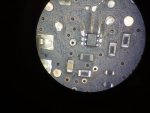
I ripped one red probe point is this one:
Question: if I plug the board in will be working good? Not sure what a probe point does, does it connect with different lines in different layers of the motherboard? Is this line so important?
What can I do to solve it?
 

Attachments

  • photo107.jpg
    photo107.jpg
    96.2 KB · Views: 0
  • photo108.png
    photo108.png
    82.8 KB · Views: 0

JorgePayar

Member
Fuck!, this motherboard is driving me crazy, but Im learning a lot.

Ok now I plug the charger I got sometimes green light, sometimes not, when I have green light I get orange light telling me that is charging.
But...before, trackpad was perfect, keyboard, leds keyboards...image and backlight...Now it is not...

Ok here begins the journey:

First I did a reset of smc: I have image, backlight, everything...trackpad is not working and fan spinning high.
Second I reboot, and I have trackpad (the fan is still spinning high) but when I click on the trackpad is not working!! before it was perfect!!

Third I reboot with D (hardware test) everything is good.
Fourth I reboot again and I have no image, no backlight....

So I guess could be the smc but it is very strange...Could be something with the power lines?

What do you recommend me to start with?

Edit: When I reset the SMC and the PRAM the screen turns on, but the fan is spinning high, I have keyboard and trackpad in Efi test, but when I click the trackpad nothing, then it switch off, I have no keyboard backlight as well and I had before.
 
Last edited:

Crizz

Member
In my early days I had a board with similar behavior as yours...
It landed on ebay since I was pretty sure it has something to do with SCM
Man I wish I could lay my hands on it again .... SORRY I was in thoughts

Back to your issue:
I've made the experience that such a behavior needs a new SMC
 

JorgePayar

Member
In my early days I had a board with similar behavior as yours...
It landed on ebay since I was pretty sure it has something to do with SCM
Man I wish I could lay my hands on it again .... SORRY I was in thoughts

Back to your issue:
I've made the experience that such a behavior needs a new SMC
Thank Crizz I have never done it before so first Im gonna try what Louis says in this video:
https://www.youtube.com/watch?v=uovnac9qYhI

anyway I think like you ,could be the SMC but before it was working ok, so confusing :S
 

JorgePayar

Member
I changed q5490 it was corroded and these are the values:

PIN 1 0V
PIN 2 3,26 v
PIN 3 16,63v
PIN 4 16,62v
PIN 5 8,24v
PIN 6 1,1mv

Pin 6 should be 1,1mv?
 

JorgePayar

Member
is dcin voltage sense failing in ASD?

I couldn't run the EFI ASD or OS ASD the mac shutdown automatically, anyway I´ve measured in diode mode the q5490 and was shorten in several pins...I remove it and it flew to the fifth dimension, I don't have another one so I need to wait until another donor board arrive 30 days or so :(
 
Last edited:

JorgePayar

Member
The board should work without Q5490. It will just run slow and fail ASD.

Ok I will try anyway I found a company that is selling the Transistor MOSFET, NTUD3169CZT5G Dual N/P-Canal, 20 V, 6-Pin, SOT-963
So probably in 2 or 3 days I will give it a try.
Duke you told me that the one wire could be bad, I did the measures in diode mode of u6900 but I don't know if they are ok, could you post the values of a good u6900 pins here?
Thanks
 

JorgePayar

Member
No Title

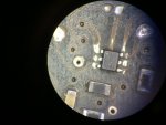
Ok I have received the q5490 but it is quite strange, I´ve soldered one and in diode mode the values are:

PIN 1: 0.00
PIN 2: 4.67
PIN3: OL
PIN 4: 4.15
PIN 5: OL
PIN 6: OL

There must be something wrong, did I put the mosfet in a wrong orientation?

Could somebody give me the correct values of q5490 in a 820 - 3115b?
 

Attachments

  • photo121.jpg
    photo121.jpg
    29 KB · Views: 0
  • photo122.jpg
    photo122.jpg
    41.5 KB · Views: 0

dukefawks

Administrator
No reason to measure diode mode. Do you have 12.6V on pin 3 with AC connected? Also why waste time on this circuit if the board is not even working right now? Q5490 does not affect basic operation.
 
Status
Not open for further replies.
Top